Visible Touch: how contact overlays reach a visual robot policy
Rendering contact as image arrows reuses a visual policy’s input pathway. The hardware and ablations show why spatial alignment, signal normalization and training still matter.
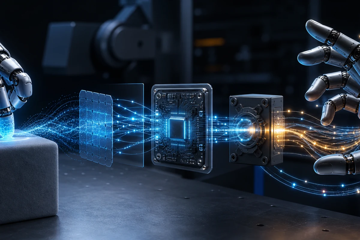
Visible Touch renders tactile measurements as colored markers and arrows on the RGB images a robot policy already consumes. It avoids adding a dedicated tactile encoder, while preserving where contact occurs relative to the scene. The important integration work moves into geometry, normalization and policy training. It is not a camera-only method. Visible Touch v1, Section 3.
This review explains that input pathway and the experiments that isolate its value. For the broader distinction between accurate sensing and successful action, see the touch-to-action evidence guide.
From a taxel to an arrow in the camera image
The method starts with each sensing element's nominal position and three-axis reading in the sensor frame. Forward kinematics and fixed mounting transforms place the sensor on the robot. Camera intrinsics and extrinsics project the arrow's tail and tip into the image. An external camera has an offline extrinsic calibration; the wrist camera's pose updates with the robot's joints. Arrows are blended into RGB with distinct finger colors. Projection derivation, Appendix A.
Simulation supplies contact-force vectors. Real hardware supplies magnetic-flux deflections, which are different physical quantities. The rendering pipeline uses normalized values and a visual scale rather than requiring force estimates in newtons. That removes one kind of calibration; it does not remove camera calibration, sensor mounting geometry or the need to train on the augmented images.
| Pipeline stage | Required information | Integration check |
|---|---|---|
| Read contact | Per-element three-axis signals and element locations | Preserve sensor identity, axis order and timestamps |
| Normalize | Unloaded baseline and demonstration-derived channel scales | Reset the baseline as specified; retain the fixed training scales |
| Transform | Sensor mount, robot joints and camera transforms | Confirm markers follow the physical fingers through motion |
| Render | Projection, arrow scale, opacity and finger colors | Check the overlay after cropping or resizing the camera image |
| Train and act | Demonstrations with the same input convention | Compare final task outcomes against matched input variants |
These checks are an implementation reading guide, not a claim that RoboSkin built the system. The tactile calibration guide explains why baseline correction, geometric registration and calibrated force are separate operations.
Magnetic hardware and training data
The real setup uses an xArm7, a parallel-jaw gripper, two RealSense D435 cameras and one 3 × 3 magnetic array per finger. Magnets embedded in silicone move relative to three-axis magnetometers. Raw magnetic flux streams at 50 Hz; demonstration and action timing uses 10 Hz. These rates describe different stages of the pipeline. Hardware and real-world protocol.
Before rendering, each channel has its unloaded offset subtracted. Its scale is the maximum absolute baseline-corrected value observed in the demonstration dataset. Scales remain fixed, while the unloaded baseline is recorded again at the start of each episode or evaluation rollout. The reported unit-to-unit variation is handled with demonstrations from the same sensor unit, not evidence of unrestricted plug-and-play sensor transfer.
The authors collected 100 demonstrations for each of four tasks and retained 397 after their acceptance and idle-trimming workflow: 97 tube episodes and 100 for each other task. Acceptance of a recorded episode is a data-quality filter, not an evaluation success rate. Input variants are applied to the same recorded sensor streams, making the comparison more informative than recollecting separate demonstrations for every representation. Table 14.
Read the final stage of each real task
The table below extracts final-stage outcomes from v1 Table 15, with 30 trials per task and condition. It keeps the tasks separate rather than treating their percentages as comparable difficulty scores.
| Complete task | Baseline | Position-only markers | Visible Touch multi-arrows |
|---|---|---|---|
| Lift | 20/30 | 22/30 | 24/30 |
| Transfer tube: insertion completed | 0/30 | 7/30 | 16/30 |
| Put mug in dishwasher: placement completed | 11/30 | 11/30 | 21/30 |
| Plug charger: insertion completed | 0/30 | 0/30 | 2/30 |
For the tube task, multi-arrows complete the picking stage in 24/30 trials, but only 16/30 complete insertion. For the charger, 18/30 reach picking while only 2/30 finish insertion. Reporting the earlier stage as full success would conceal the main remaining difficulty.
Position-only markers improve tube insertion from 0/30 to 7/30 without the full contact vectors. Some benefit therefore comes from spatial cues. Multi-arrows improve further to 16/30. A separate tactile-view image yields 0/30 tube insertions, illustrating that how the contact signal reaches the policy matters. Binary-contact and bar variants also trail the real-world multi-arrow condition. These ablations help separate contact content from presentation, although 30 trials per condition still leave uncertainty.
The best overlay changes between simulation and hardware
In the BC-Transformer simulation comparison, an averaged arrow outperforms multiple arrows across the reported suites. On real hardware, multiple arrows perform better. Simulated contacts can appear at changing mesh locations; physical taxels have fixed locations and a different signal distribution. An aggregate that helps one representation need not preserve the details needed by the other. Simulation Table 2.
The miniVLA headline also needs version discipline. The project page reports a 28.9-percentage-point gain, while v1 Table 1 reports 50.9% versus 76.2%, a 25.3-point difference. This review uses the explicitly versioned v1 table. Its baseline entries are the strongest available single runs per suite, whereas the headline Visible Touch values average five training seeds. That asymmetry limits how confidently the aggregate can characterize variability. v1 Table 1; official project.
What is available to reproduce
The paper calls the hardware open source, but the official project page checked on September 19, 2026 did not expose a verified code, CAD or dataset download. The linked miniVLA repository belongs to an underlying policy, not a confirmed release of the complete Visible Touch pipeline. Code, hardware-asset and dataset licenses therefore remain unverified. Use the dataset directory to distinguish a described collection from an accessible resource.
Before budgeting a reproduction, locate the actual sensor files and license, match the camera and mounting transforms, preserve preprocessing, and obtain the training and rollout configuration. The paper's bill of materials is useful context but not a supplier quote or a verified downloadable hardware package.
This review uses the September 12, 2026 v1. The arXiv record reports CoRL 2026 acceptance, while the project retains anonymous/submitted wording. Proceedings were not independently verified. All results are the authors' experiments; RoboSkin has not built or independently evaluated this system. The tactile AI guide places this rendering approach alongside dedicated encoders and reactive controllers.
Sources
Continue the topic