Materials and mechanisms
Electronic Skin: Materials, Sensing Mechanisms and Uses
Electronic skin is a conformable sensing system that converts physical stimuli at a surface into electrical signals. Electronic skin can be mounted on a robot, a prosthesis or a wearable, so it is broader than a robotic covering. This page compares materials and measurement mechanisms; the robot skin guide covers whole-robot integration and vendor choices.
Last updated:
Published | Updated by RoboSkin.ai Editorial Team
November 4, 2026: added a material-to-controller measurement chain and source-reviewed textile/hydrogel comparisons. No device testing or reproduction claimed.
- 4
- sections
- 3
- questions
- 3
- next routes
Short answer
What you need to know
- 1
A flexible substrate alone is not electronic skin: the system needs sensing elements, electrical readout and a defined measurement.
- 2
Pressure, strain, temperature and vibration may require different sensing elements. One successful laboratory channel does not prove all of these capabilities.
- 3
Use robot skin for the complete installed covering and electronic skin for the sensing material or device architecture. The terms overlap when electronic skin is installed on a robot.
Topic 01
Electronic skin versus robot skin
This distinction keeps material research separate from claims about a finished robotic system.
| Dimension | Electronic skin | Robot skin |
|---|---|---|
| Primary scope | Conformable sensing materials, devices and readout | Covering installed on a physical robot |
| Possible host | Robot, prosthesis, wearable or test fixture | Humanoid, robot arm, hand or other robot body |
| Typical evidence | Sensitivity, range, hysteresis, drift and bending tests | Coverage, wiring, durability, calibration and controller use |
| Mechanical requirement | Flexibility or stretchability appropriate to the device | Mounting, replaceability, abrasion resistance and safe contact |
| What is not established | A material demonstration does not validate a robot policy | A soft cover does not establish distributed tactile sensing |
Topic 02
How the sensing mechanisms work
Piezoresistive devices change electrical resistance under deformation; capacitive devices change capacitance as electrode geometry or the dielectric changes. Piezoelectric devices generate charge under changing mechanical stress, while triboelectric devices use contact electrification and separation. The device structure and readout determine whether static pressure, dynamic contact or both can be measured. Sensor output still needs calibration, drift assessment and separation from bending or temperature effects.
| Mechanism | Typical material or structure | Measurement consideration |
|---|---|---|
| Piezoresistive | Conductive composite, resistive network or patterned conductor | Separate contact response from strain, hysteresis and drift |
| Capacitive | Electrodes with a compliant dielectric | Control parasitic capacitance, geometry and readout coupling |
| Piezoelectric | Piezoelectric polymer or ceramic structures | Charge leakage and electronics affect low-frequency response |
| Triboelectric | Paired contact surfaces with electrodes | Signal depends on contact history, separation and environment |
Topic 03
Trace the measurement from material to robot decision
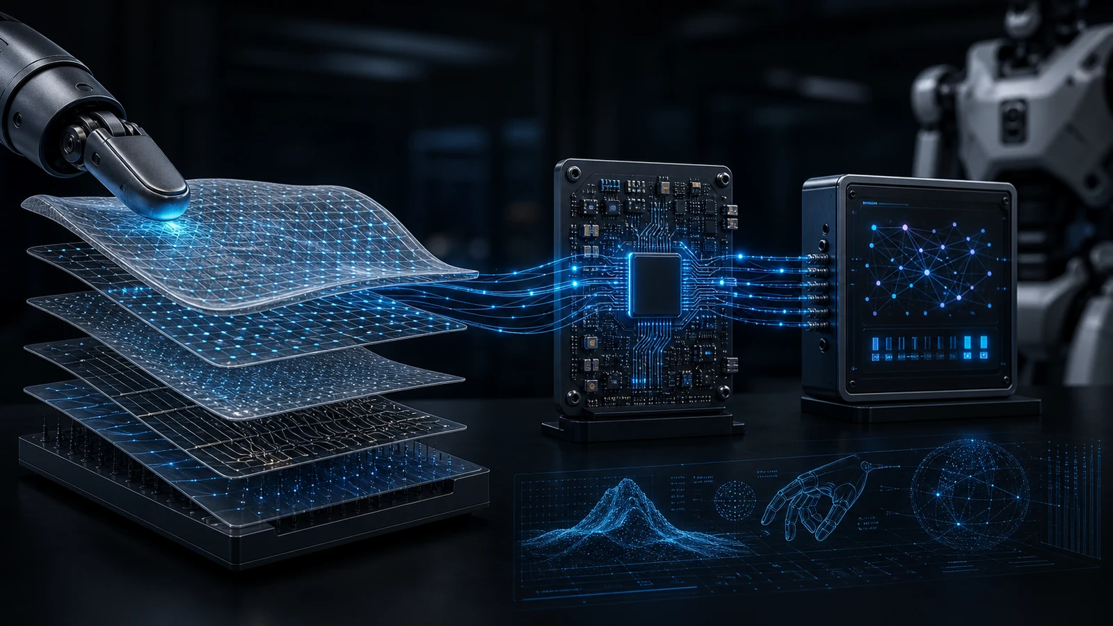
Electronic skin becomes useful through a measurement chain: a physical interaction changes an electrical signal, readout electronics acquire it, calibration or a learned model estimates a quantity, and a host system decides what to do. A strong result at one layer does not validate the layers after it.
Mannsfeld and colleagues’ 2010 capacitive-sensor study shows why structure belongs in the specification: microstructuring the compliant dielectric changes its response relative to an unstructured film. This does not give every microstructured device the same range, accuracy or lifetime. Use the original specimen, loading interval and readout conditions when comparing a sensitivity claim.
| Layer | Evidence to retain | What it cannot establish alone |
|---|---|---|
| Material and mounting | Composition, geometry, electrodes, attachment and loading conditions | A reference calibration after recasting, remounting or replacing the cover |
| Electrical acquisition | Measured variable, selected channels, scan schedule and timestamps | A simultaneous full-surface refresh rate from the fastest single-channel rate |
| Estimated quantity | Reference instrument or labels, model version, calibration and evaluation split | Force accuracy from a classification or touch-localization score |
| Host behavior | Which estimate reaches the controller, with what delay and failure handling | Robot task performance or safety from a sensor-only demonstration |
Two research architectures, two different interfaces
The single-material hydrogel hand uses distributed impedance measurements and selected information channels to infer interactions. Its millions of available amplitude/phase channels are not millions of physical taxels. Its response also depends on contact conductivity and environmental conditions. A new geometry or electrode interface requires new evidence.
The three-channel textile instead combines triboelectric touch localization with a resistive pressure channel in a wearable human–robot interface. A person commands the arm through the textile; this is different from measuring the arm’s contact with its surroundings. Self-generated localization signals do not power the complete readout and actuation system.
A useful comparison holds the intended decision constant
Start with a decision such as detecting contact onset, estimating a sustained load or locating a human command on a wearable. Specify the reference quantity, contact material, surface region, mounting state and required update interval. Compare candidate devices under that same question; do not rank a classifier, a force sensor and a wearable command surface by one sensitivity number.
For a proposed installation, keep unloaded drift, repeated loading/unloading, bending without contact and contact under the intended mounting as separate observations. Record which behavior changes after replacement. These are suggested engineering comparisons, not tests performed by RoboSkin.ai, a certification protocol or proof that a device is suitable for a medical or safety application.
Topic 04
Materials and uses
Elastomers provide compliance; conductive fillers, films or patterned electrodes provide electrical pathways. Microstructured surfaces can change contact area and sensitivity, but quoted sensitivity must be tied to a pressure interval and loading method.
Robot contact patches, prosthetic interfaces and wearable measurement patches place different demands on packaging, wiring and durability. For a robot, evaluate repeated loading on the actual mounting surface and check how replacement or bending changes the calibration.
| Use | Relevant observation | Evidence to request |
|---|---|---|
| Robot fingertips or body patches | Local pressure or distributed contact | Coverage map, timing, calibration and repeated-load data |
| Prosthetic interfaces | Contact or fit at the interface | Mechanical compatibility and application-specific validation |
| Wearable research patches | Deformation or surface stimuli | Drift, attachment conditions and comparison with a reference |
Common questions
FAQ for this topic
Does a large channel count mean many physical taxels?
No. A channel may be an electrical configuration, amplitude, phase or derived feature. Report physical sensing locations, selected readouts and simultaneous update rate separately. The hydrogel example uses many configurations around only 32 electrodes.
Are electronic skin and robot skin synonyms?
They overlap but are not interchangeable. Electronic skin describes the sensing device architecture; robot skin describes the installed covering and its integration on a robot.
Does high sensitivity prove useful robot touch?
No. The usable force or pressure range, spatial coverage, bandwidth, hysteresis, durability and controller integration must also match the task.